Home
AGS
LVDC
Gemini
Download
Document library
Change log
Bug and issues
Developer info
Virtual AGC — AGS — LVDC — Gemini

Physical Implementations
John Pultorak's Famous Block I AGC
... and more!
FAQ
yaAGC
yaYUL
yaDSKY
yaOtherStuff
Luminary
Colossus
Language Manual
Physical Implementations

Please enable javascript in your browser to see a site-search form here.
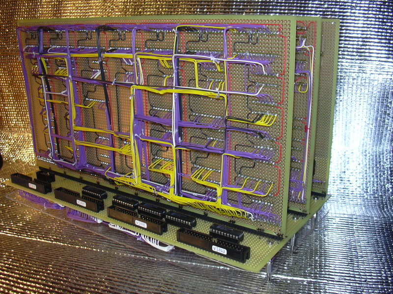
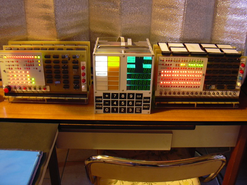
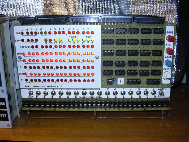
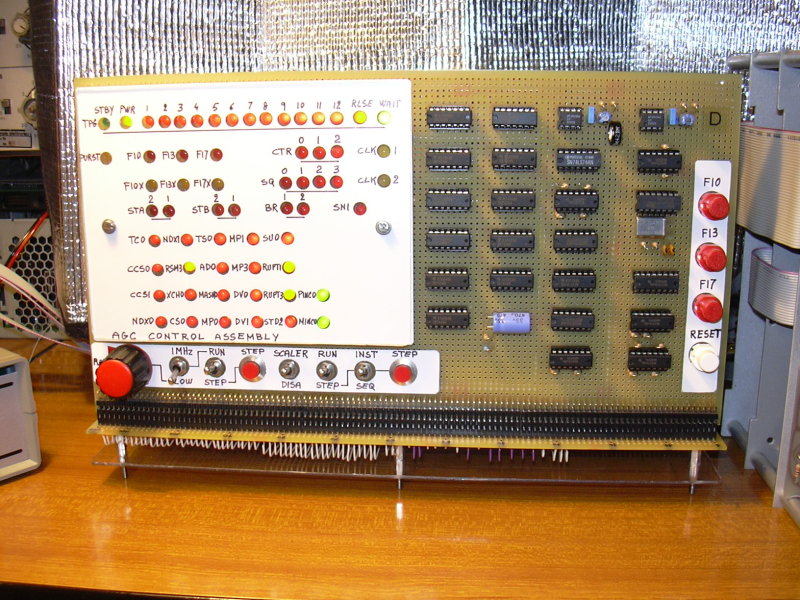
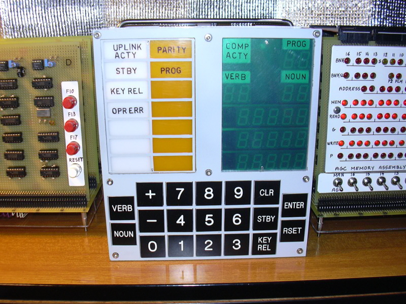
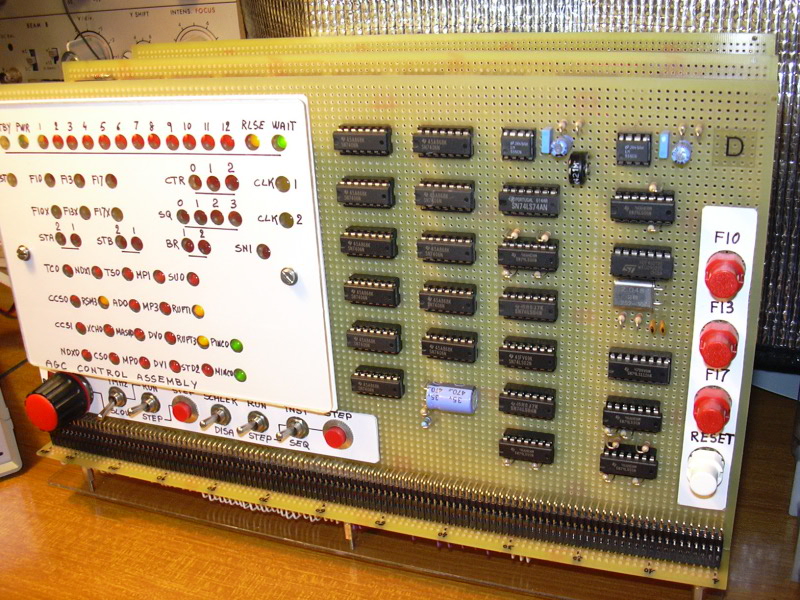
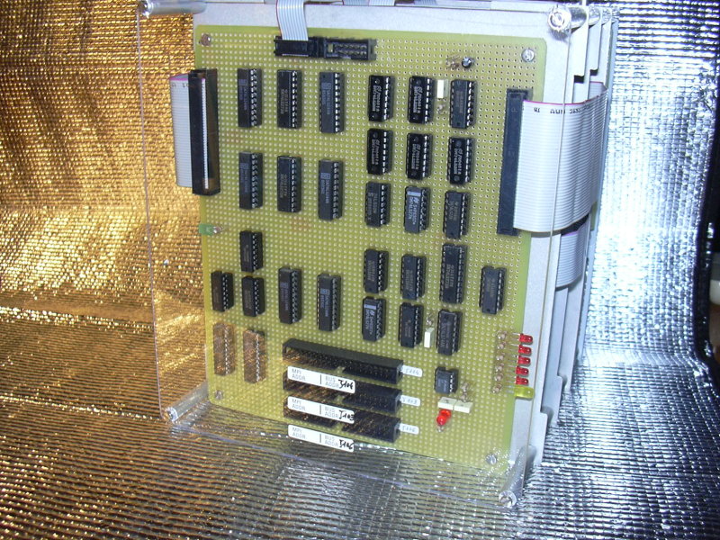
Contents

This page is devoted to physical implementations of the Block I and Block II AGCs, and their peripherals such as DSKYs.  In other words, to physical devices that you could build and keep in your living room to impress friends and neighbors.  Be the first on your block to have one!

John Pultorak's Block I AGC Project

The Pultorak PDFs

John Pultorak and his AGCJohn Pultorak has constructed a physical (not virtual), working model of a Block I AGC out of 74LS-series low-power Schottky TTL devices.  The model works, and runs software which John has adapted from Colossus 249 software.  John's unit even has the same general appearance as the original Block I AGC prototype!  Of course, Colossus 249 software is targeted for the Block II AGC rather than the Block I AGC, but then nobody seems to presently know the whereabouts of any Block I AGC software source code.  (If you do know where any Block I code is, let us know!)

No manned mission ever flew with a Block I AGC.  It was originally intended that Apollo 1 and Apollo 2 would be Block I missions; but I'm sure you know what happened to Apollo 1, and Apollo 2 never took place.

John has thoughtfully provided us with his schematic diagrams, with adapted Block II software, and with his cross-assembler.  You can read all about it—or as you'll see below, mostly about it—at the various mirror websites hosting John's docs:
At the present time (12/26/04), what you'll find on these websites is a series of PDF files documenting John's project.  I'll refer to these as the Pultorak PDFs.

How is this Related to Virtual AGC?

It's not.  John's project is not an offshoot of the Virtual AGC project, or vice-versa, and neither project uses materials created by the other.  But John's project is at an end, and he doesn't want the hassle of maintaining a web presence for it, whereas Virtual AGC is an ongoing project.  Nor does John maintain any of the websites mentioned above.  So as a courtesy, the Virtual AGC website is going to host supplemental materials for the Pultorak project that haven't yet worked their way into the other websites mentioned above.

The Supplemental Materials

Copyright and Licensing

The Pultorak PDFs do not address the question of copyright for the software or schematics, nor the conditions under which they may be used by others, though the webpages themselves are copyrighted by John.  John has told me that he wants everyone to be able to use the software and hardware freely.  Click here to see an email in which he explains this.  (And just in case you wonder about the context, click here to see email containing my copyright/licensing questions to which he is replying.)

AGC Source Code

AGC source code (flight software adapted for Block I and for John's cross-assembler, test & checkout software, and so forth) is provided in the Pultorak PDFs.  But the PDFs often provide assembly listings—i.e., reports generated by the assembler—rather than pure source code.  An assembly listing isn't a legal assembly-language source-code file, so you can't conveniently change and reassemble it.  You can get a zipfile containing the source code and some supplemental files (such as hex files) by clicking here (1 MB). 

Unfortunately, the format accepted by John's cross-assembler isn't compatible with yaYUL (or vice-versa), so these source files cannot be assembled by yaYUL.  They must be assembled using John's cross-assembler.

Assembler and Simulator Source Code

The C++ source code for John's PC-based cross-assembler and simulator do appear in the Pultorak PDFs, but rather than cutting-and-pasting you may find it more convenient to download a zipfile by clicking here (3.7 MB).

Circuit Design

The Pultorak PDFs do provide schematic diagrams, but some readers have commented that it is difficult to make out some of the details in them.  You can download a zipfile containing the complete CAD files for the design by clicking here (1.7 MB).  The CAD files are in Circuitmaker format (*.ckt), but even if you don't have a copy of Circuitmaker, the zipfile may be worth downloading because it also contains:
At the time John created these materials and first sent them to me, Circuitmaker was available commercially, and if you couldn't affort the full version of the program you could either have downloaded the free but limited "student" version of the software, or else you could download a full but time-limited demo version of the program.  Since that time, however, the company which was selling Circuitmaker has apparently been acquired by Altium, and the Circuitmaker program has been discontinuedAccording to Altium's website, the substantially more expensive Altium Designer product is supposed to be able to import existing Circuitmaker schematics.  I have no idea whether this is true or not, though my past experiences in such situations leads me to be suspicious about it.  If anybody else has tried it (and cares to convert John's schematics for me), please let me know.

In order to run Circuitmaker, you have to use Options/LibraryLocation (full or demo version) or File/Preferences/DirectoriesAndFiles (student version) on the menu to set the location of the "user library" (USER.LIB) that comes in our zipfile.  (After doing so, you will probably also have to exit from Circuitmaker and then re-run it, because Circuitmaker will already have loaded the default USER.LIB into its internal cache, and it won't reload it until being restarted.)   Otherwise, when you load the schematics they will have wires but no electrical components on them.  Incidentally, although Circuitmaker2000 is a Windows program, both the student and demo versions run just fine under Linux with CrossOver Office.  They may run fine too under normal Wine, but I haven't tried it.

One thing you will likely want to do with Circuitmaker is to create a netlist.  Neither the student nor demo versions of Circuitmaker seem to want to admit the notion that a single IC can contain multiple gates, and will therefore likely display an error prompt asking if you want to "correct" this condition.  If you say "yes", Circuitmaker will arbitrarily relabel the components within the schematic, so that only one gate appears in each package.  My advice would be to say "no" (not to correct), as the only negative side-effect of doing so appears to be that the netlist file will have duplicate entries for the packages with multiple gates, but the wire-list will be correct.


Dimitris Vitoris's Block I and Block II AGC Project

The project of Dimitris ("Jim") Vitoris takes over where John Pultorak's project stops.  The project is still in its very first stages, so please don't take any statements made here as commitments!  But the basic idea of the project is to be able to create a physical implementation of a Block II AGC and DSKY, which (unlike John Pultorak's Block I AGC above) can be constructed by hobbyists, without requiring the immense skill needed to construct a Pultorak AGC.

Here is a very uncertain roadmap of the project.  It may be that all of these phases will be completed, or it may be that the project will stop where it is now.  Or perhaps some phases might be skipped.  There is no timetable.  But however it goes, thanks Dimitris!

Project Phase
Description
Status
A0
Conversion of John Pultorak's Block I AGC design (schematics only!) to Eagle CAD, with corrections and small improvements.
Ready now!
A1
A clean restructuring of the Block I design -- for example, with AGC, DSKY, and monitoring busses separated into independent assemblies rather than being a part of one large assembly.
Preliminary data available.  (See change log.)
B0
Block II AGC design (schematics and printed-circuit board layout!) using 74xxx TTL logic.
Possible
B1
Size reduction of Block II design, using surface-mount parts and FPGAs.
Possible
C0
Further, final size reduction of the Block II design, with added Virtual AGC compatibility.  (This would mean, for example, that one of Dimitris's physical DSKY could be used with a PC running Virtual AGC.)
Possible

Download 20080205 snapshot now!

The download is a zipfile containing the complete set of materials that have been created by Dimitris so far.

Dimitris uses Eagle CAD for this project (www.cadsoft.de).  Eagle is a cross-platform program that is available for Linux, Windows, and Mac OS X.  While Eagle is a proprietary program that costs money to purchase, there is a free version that can be used with small designs.  I have verified that the free version does allow viewing of the phase A0 schematics on Linux.

Once phase B0 and beyond are reached, it would be valuable to have mechanical design and drawings of things such as DSKYs, enclosures, front panels, and so forth, so that complete physical units can be constructed.  Any mechanical engineers who are interested should contact me at the email address at the bottom of this page.  Mechanical design of a Block II DSKY in particular would be useful, regardless of the how far Dimitris cares to advance his project.

Dimitris has also sent some photos of the physical device he is constructing:


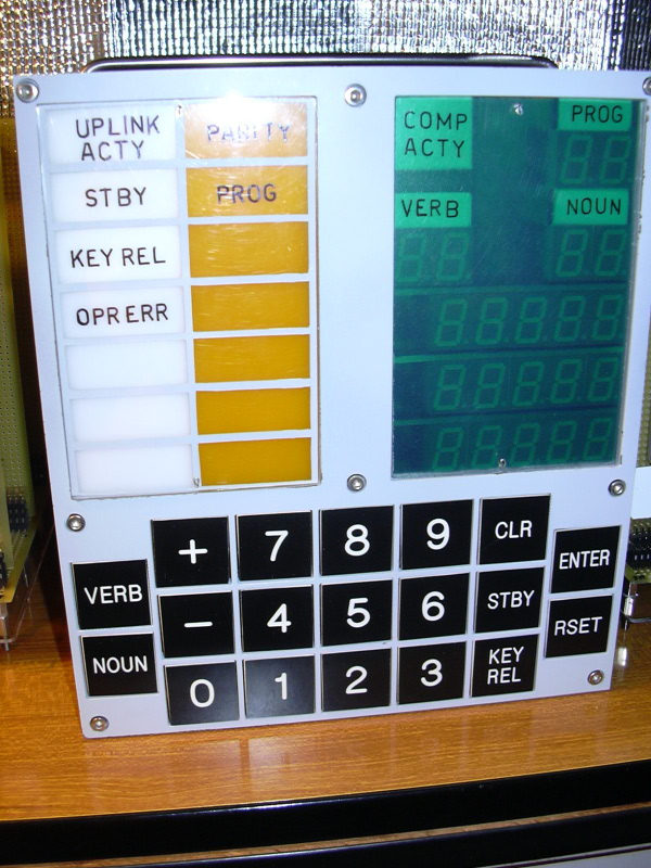
The physical faceplate, work in progress!

Cleaned-up stylized drawing
from which measurements can
be taken.  A CorelDraw file is also
available.

Dimitris mentions that his best estimate of the faceplate dimensions is 18.9 cm (7.44 in.) wide and 21.8 cm. (8.58 in.) high, and points out that additional dimensions can be extract from the right-hand drawing above.


Philip Schmidt's Block I AGC Project

Philip Schmidt has also been kind enough to let us know about his Block I physical implementation.  You can see his write-up of what he's been doing at his own web-page.  Phil tells me that he will eventually provide all of the CAD files for his design (in Altium Designer format), but for right now it's all PDFs while it's a work in progress.


Who's Building Them? (Alessandro Cinquemani)

Of course, the great thing about these projects is that you can start from them and build your own AGC or DSKY.  If you have done so, feel free to send me some photos and/or descriptions of what you've built.  Where is Heathkit when you need it?

Alessandro Cinquemani of Aviano, Italy, has sent in the very nifty photo (click to enlarge) seen below.

Click to enlarge.

As I understand it, here we're seeing the DSKY and CTL modules, which Alessandro built by following through on John Pultorak's documentation.  Alessandro is still working on the MEM and PROC modules, but when the AGC is fully operational is considering making actual circuit boards.  Great job, Alessandro!

Update:  Recently, Alessandro has sent us a whole gallery of photo updates, reluctantly down-sampled by me to save some space.  He tells us (2009-06-17) that he thinks he may be able to finish it up in 3-4 months.  Click'n'enjoy:


Other?

My personal bias is that I'd prefer it if these materials were available for use with a free and open-source CAD system rather than proprietary systems such as Circuitmaker and Eagle.   The subsequent discontinuation of the Circuitmaker program (mentioned above) puts the problem in stark relief:  John Pultorak spent a lot of time creating these materials, and yet within just a few years nobody will be able even to open the CAD files he created.  This website deals with things that happened (as of this writing) 40 years ago, and I'd like the  information presented here to still be useful 40 years from now ... or 400.  But the CAD files have proven to have a shelf-life of less than 5!

Such absurd situations should come as no surprise to anybody with substantial experience in using electrical CAD systems.  Speaking from experience, every proprietary electrical CAD program is eventually discontinued either by virtue of acquisition of the manufacturer or else a strategic decision by the manufacturer, and the schematic format is then orphaned, usually even without any documentation.  Yet I've never encountered an electrical designer who had noticed this fact or believed it was a problem; instead, CAD software is invariably chosen on the basis of whatever features are most convenient to the designer at that moment in time.   Indeed, I've made such selections myself, based on whatever software has the fastest or best autorouter.  But the autorouter relates only to PCB layout, and has essentially no relation to schematic capture, which could be done by a separate program from the PCB layout program entirely. Schematic capture and PCB layout are interrelated only by exchange of netlists and back-annotation info, and the notion that the two must be integrated into one program is a fantasy promoted by CAD manufacturers and swallowed en masse by circuit designers.  I'd venture the advice that if you're going to use a proprietary CAD program, it's best to use one that supports the Orcad file format, and to archive your work in that format, since it's the closest thing to a de facto standard that exists at the present time.

It would be nice if an open-source CAD tools were used instead, so that the schematics, PCB layouts, etc., would be freely editable by everybody without purchasing a proprietary tool.  If anybody wants to convert the CAD files into a more open format, your help would be welcomed.  I highly recommend that the target schematic-capture format should be that of the free open-source tool gEDA.  Of course, if you absolutely insisted, we'd be happy to have Orcad, or any other format as well!  I've so far not found an automated tool to perform the conversion of Circuitmaker or Eagle to any other format.  (If you wanted to write a program that converted Circuitmaker or Eagle files to gEDA or some other format, I'm sure that would be even more valuable than the conversion itself.)

Last modified by Ronald Burkey on 2009-08-17.

Virtual AGC is hosted by ibiblio.org